AWS for M&E Blog
AWS Artist Series: Creating characters with dynamic wrinkles
Spanner is the story of two bridge builders, Noa and Ulysse. Ulysse is trying to learn from Noa, but he’s too proud and foolish to ask her directly. This leads to him inadvertently being tossed off of the bridge. Later, Noa saves Ulysse and then wraps him up and sticks him under the bridge as her new tool caddy, since he had to “learn the hard way.”
This project was born out of the need to create a full-scale production, at the highest quality possible, for end to end testing of the Amazon Nimble Studio service. Our goal was to create a short film that is visually beautiful, computationally complex, and to push all facets of the product—just as our customers push their own productions. We did so to prove that the product is truly ready for customers, and verifies that they don’t need to compromise to create their own productions at the highest level of quality using Nimble Studio.
We encourage you to watch our short film Spanner and then review the following to see how the dynamic wrinkling system was created for our characters.

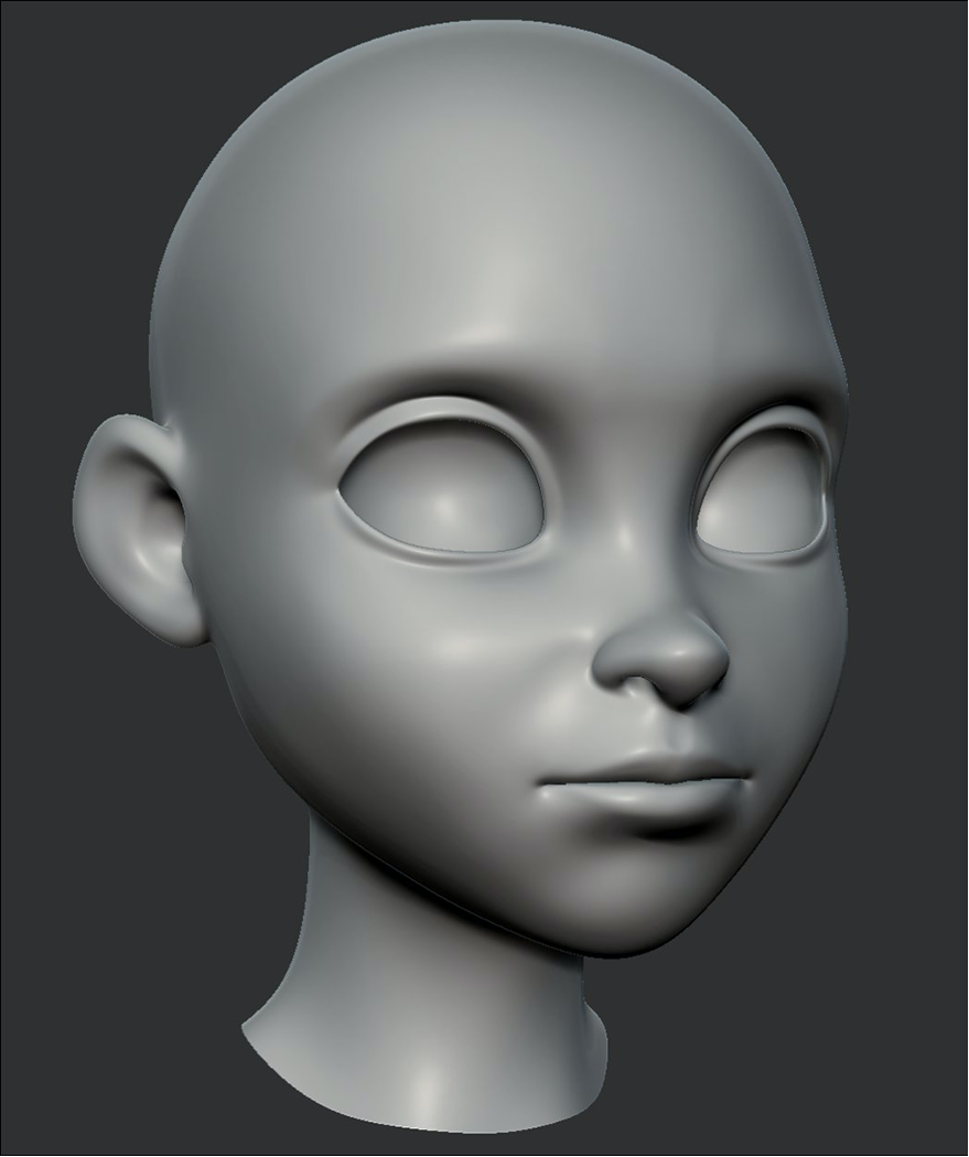
Noa from Spanner
Overview
The particular issue we are trying to solve in this post is the creation of dynamic forehead wrinkles for the characters. This means that we need to have forehead wrinkles appear and disappear as the character moves their eyebrows up and down. When both brows are moving up, the wrinkles should appear over the whole forehead. When one of the brows is raised, the wrinkles should appear only over that same side of the forehead.
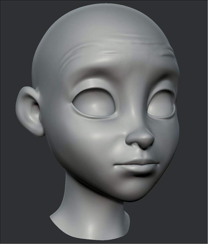
In the following image, you can see Noa’s forehead wrinkling as she makes a surprised expression.
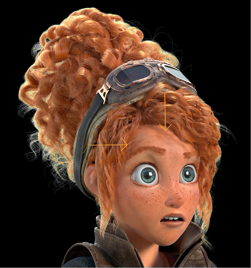
Surprised Noa
By creating a dynamic wrinkling solution, we create higher-quality characters. If done effectively, the solution also keeps the rig lightweight for animators and reduces the workload for animators to blend these wrinkles in by hand.
Now let’s go through a step-by-step explanation of how to set up the dynamic wrinkles from beginning to end.
Prerequisites
Ideally you already have access and a decent idea of how to use Autodesk Maya and Pixologic’s ZBrush. If you don’t use Maya or ZBrush, you can still gain a better understanding of the methodology behind creating the dynamic wrinkles, and apply the same concepts to other 3D packages.
If you’d like to test this out on Noa, use the Testing with AWS assets using Autodesk Maya 2020 tutorial to get the Noa asset and follow along. If you’re interested, you can also check out Amazon Nimble Studio to build your own studio in the cloud.
Creative solution overview
The idea is to create the dynamic forehead wrinkles without putting any burden on the rigging, which would slow it and the productivity of the animators down. Each feature added into the rig comes at a performance cost. Meaning that, as the rig becomes increasingly complex, the time it takes to visually update in the viewport slows down. This is a burden on animators because they need the rig to playback at 24 fps to get real-time feedback on the quality of their animations.
We also don’t want to create an additional attribute for animators to try to animate, which also slows down their work. Taking all of this into account, if we can get the wrinkles to happen at render time as well as have a feedback option for the animators to turn the visibility of the dynamic wrinkles on and off, we have a solution that is both performant for animators and delivers a high-quality visual.
To accomplish this, if we can connect the eyebrow controls to shader attributes and use the positions of the eyebrow controls to drive the amount of displacement occurring on the forehead, we can get wrinkles to happen at render time and create a rigging and animator-friendly solution.
By creating a solution that happens through textures at render time, we reduce the need for extra resolution of the geometry in the rigging and animation steps of the pipeline to gain the same visual improvements. This lowers the overall poly count of the characters, and evenly spaces the topology throughout the forehead, which in turn keeps the rigs performant, and animators happy.
Approach
Step 1: Create custom attributes
To start creating the dynamic wrinkle system, we first need to create custom attributes on the character’s rig that are driven by the translation in Y of the eyebrow controls. The Y axis is denoted in green on the gizmo in the following image. It controls the upward (increasing values in Y) and the downward (decreasing values in Y) movement of the eyebrow.
Translation gizmo
There are five different custom attributes created and driven by the eyebrow controls. These were placed on the model group of the character so that as the character moves through the different stages of the pipeline, they are always accessible to the rig and the skin shader.
Create a custom attribute on the model group
- Open the Outliner.
- Select model_grp.
- Open the Attribute Editor.
- Choose Attributes → Add → Attributes.

Adding custom attributes
We add each of the five attributes listed in the preceding image. In the following image, you can see the setup for the L Brow In (l_browIn) custom attribute. Note that the Data Type is set to Float and the Minimum and Maximum values are set to 0 and 1, respectively. This means that any negative value of the eyebrow control is not taken into account for our custom attribute.

Adding custom attributes for the different brow controls
As you can see from the following image, we created custom attributes for the L Brow In, L Brow Out, M Brow Mid, R Brow In, and R Brow Out. These are the outer and inner controls on the brow and the one in between. We drive these five attributes by their corresponding eyebrow control.

Custom brow attributes
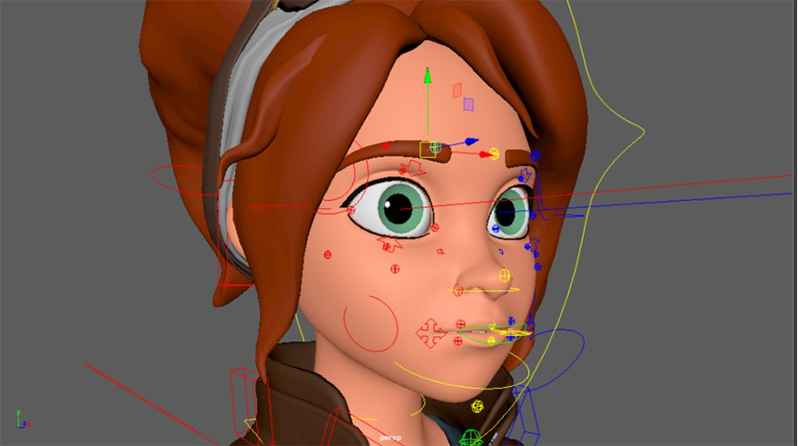
Eyebrow controls
Step 2: Create the connections between the custom attributes and the rig
Next, we set up the connections between these attributes and the eyebrow controls.
- In the Maya header menu, select Windows → General Editors → Connection Editor.
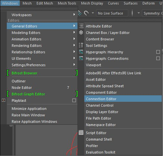
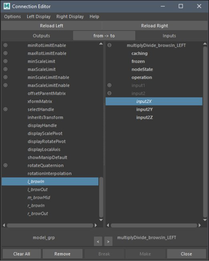
Connection editor
- In the Connection Editor menu, selectmodel_grp from the Outliner.
- Choose Reload Left.
- This places all of the attributes for the model_grp on the leftside (the to side) of the Connection Editor.
- Select the l_browIn_ctr and choose Reload Right.
- In this case, we chose the l_browIn_ctrl to load into the right side (or from side) of the editor. We want to use the translate Y value from this control to drive the l_browIn attribute.
- Select the translateY from the right side of the menu.
- Then select l_browIn from the left side.
- This creates a connection between the two values.
Note that our connections are going from the right side of the menu to the left side as denoted in the middle of the Connection Editor on the to ← from button. You can use this to toggle the direction of to ← from.

Setting up connections
When the eyebrow controls are at their rest (or default) position, the value of the Y axis is 0. The controls are normalized so that when the translation reaches a value of 1 in Y, the control is at the maximum reasonable height for brow movement. This allows us to drive the custom attributes between the 0 and 1 values as well, which makes it much easier when doing the math in the shader to control the amount of displacement. For the brow movement, we’re only interested in the movement upward of the brow control because it causes the compression of the skin on the forehead and causes our wrinkles!
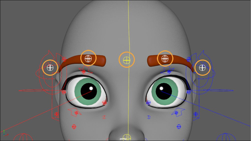
In the following image, the r_browIn_ctrl, l_browIn_ctrl and m_browMid_ctrl are moved upward. These are the three controls denoted by the orange circles in the following image. As you can see highlighted in the following image, the custom attributes L Brows In, M Brows Mid and R Brows In have all increased in value as they are being driven by the eyebrow controls.
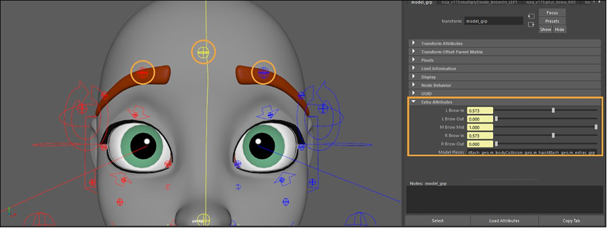
Brow controls translated up in Y axis
Step 3: Create the displacement texture
Now that our custom attributes are being driven by the rig, we can use these attributes in the skin shader to drive the displacement.
- Raise all of the brow controls of the character to a Y value of 1.
- This is the maximum height of the control and since we are blending in the displacement, we want to start with a fully raised brow and then blend in the wrinkles in the shader as the brow controls move upward.
- Export the geometry of the character in this “brows raised” pose.
- In ZBrush, we can use this “brows raised” geometry as a layer blend so that as we’re sculpting, we can manually change the value of the blend layer between 0 and 1 and “raise the brows.” On this fully “brows raised” shape, we can then sculpt in wrinkles and bake out the displacement texture.
By doing all of the eyebrows raised at once in the sculpt, we ensure that the wrinkles align perfectly through the middle of the forehead no matter what part of the brow is raised. If we create a different displacement texture for each brow section, it would be much more difficult to achieve a perfectly contiguous wrinkle across the forehead.
Note that we also create this displacement texture on a “clean” version of the head. This means that there are no moles, scars, skin pores, etc. on the model at the time that the forehead wrinkles sculpt. By using this clean version, there are no other features being displaced on the character’s face when this forehead displacement texture is used. If there were other features still in this displacement texture, then they would also become more pronounced as the eyebrows are raised.
ZBrush – Brows down
In the following image, you can see how the brows are raised and the wrinkles are sculpted into the forehead. We can then export the forehead wrinkle displacement texture from this sculpt. We don’t need to worry about any other features of the face being negatively affected because next we create textures to control the area of influence that this displacement texture has. Therefore, the displacement only shows up where we want.
ZBrush – Brows Up
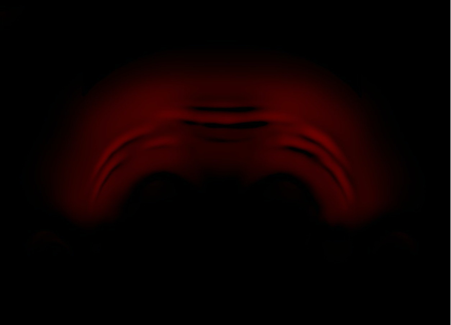
Forehead displacement texture
We use this displacement texture in the shader to control the look of the wrinkles. Now we need to create the ability to control on what section of the forehead the wrinkles appear.
- Create three textures that use color values (black being 0, white being 1, values of grey in between) to control where the wrinkles appear.
- We can use these textures with math nodes in the shader to multiply the wrinkle values. So, if the right eyebrow is raised, only the right side of the forehead wrinkles because these areas of influence textures multiply the white area by 1 and the rest of the face, which is black, by 0.
In the following image, you can see the different areas of influence we created. The wireframe of the head UV is displayed for better clarity. There is a left, middle, and right area of influence texture.
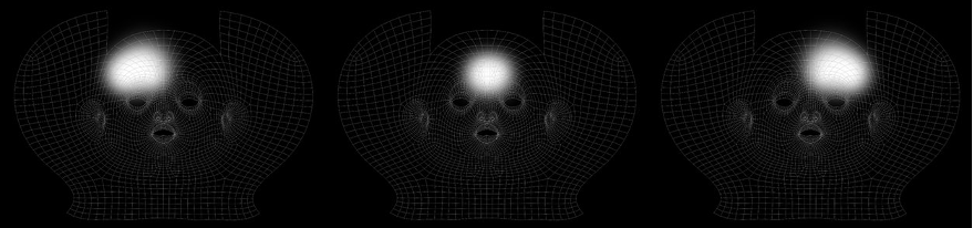
Area of influence textures
Step 4: Shader network setup
Now it’s time for us to set up the displacement shader network. In the Node Editor, we bring in each of the three areas of influence textures.
- Connect the Out Color R from each area of influence texture to the multiplyDivide node Input 1X for the corresponding place on the forehead where we want the displacement to show.
- This means we have multiplyDivide nodes for browsIn_LEFT, browsOut_LEFT, brows_MID, browsIn_RIGHT, and browsOUT_RIGHT, which are connected to one of the three areas of influence textures (lefts with left, rights with right, and the mid with mid) as shown in the following image.
Remember that the values coming from the custom attributes are 0 to 1 and inform the shader how much the wrinkles should displace. A value of 0 is no displacement and a value of 1 is full displacement.

Shader Network – Area of influence texture connections
- Middle mouse drag the model_grp from the Outliner into the Node Editor.
- Next, connect the custom attributes from model_grp that we created earlier to the corresponding multiplyDivide node’s Input 2X.
- For example, L Brow In would be connected to multipleDivide_browsIn_LEFT as in the following image.
- Do this for each of the five custom attributes.
Shader network model_grp to multiplyDivide connection
Through the shader network that we created so far, we set up where the wrinkles happen through the area of influence textures, and how much they happen through the custom attributes. By multiplying the two values together we have a value for where and how much the wrinkling should take place.
We now take the Output X from each of the multiplyDivide nodes and connect them into the plus_brow_MIX. This is a plus node created in the Maya shader network and is used to add all of the values coming from the different parts of the forehead together. This gives us a value for how much and where the wrinkling is taking place over the forehead as a whole instead of the individual parts.
You can see this connection in the preceding image Shader Network – Area of influence texture connections.
Now that we have a value for where and how the displacement occurs for the whole forehead, we want to then multiply this value by the wrinkle displacement texture. This gives us where the wrinkles occur, how much they displace, and the shape of the wrinkles all together in a single value.
This is done through another multiplyDivide node, named multiplyDivide_RESULT, in the Maya shader network. The displacement texture, in this case noa_brows_raised_02.exr, connects to this node. The result gives us where the wrinkles happen and what they look like.
- Connect the noa_brows_raised_02.exr from its Color R value to theInput 1 X value of the multiplyDivide_RESULT node.
- Connect the Output 3D X value of the plus_brow_MIX node can be connected to the Input 2X slot of the multiplyDivide_RESULT
- You can see this connection in the following

Shader Network – Brow displacement connection
- In between the plus_brows_MIX node and the multiplyDivide_RESULT node add a remapValue node.
- This node gives us a curve to adjust how quickly the wrinkles are being created.
- Add another multiplyDivide node.
- Rename this node multiplyDivide_PUSHRESULT.
- Connect the Output Value of the remapValue node to the multiplyDivide_PUSHRESULT
- Connect the Output X of the multiplyDivide_PUSHRESULT node to the Input 2x of the multiplyDivide_RESULT node.
- This additional multiplyDivide_PUSHRESULT node allows us to adjust the total amount of displacement.
These two additional nodes aren’t necessary to achieve the effect, but they are great to tweak the final result.
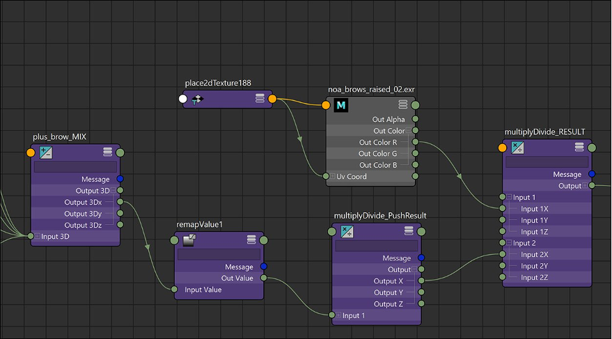
Shader Network – Adding polish nodes
As you see in the following image, the final step is to use the value created by the multiplication of the overall forehead wrinkle value and add that to the base displacement texture, which has all of the pores, moles and scars that the character has all the time. We do this through a plusMinusAverage node (set to Sum). After that, we can connect the plusMinusAverage node to the DisplacementShader node, which results in dynamic forehead wrinkles on the character!

Shader Network – Displacement value connections
And the following is the whole displacement portion of the shader network.

Displacement Shader Network
Results
If we want to see the displacement live, we can do that too.
- Select the m_skin_geoShape.
- Under the Smooth Mesh dropdown in the Attribute Editor choose the Displacement Preview check box.

Displacement preview option
This turns on a live preview of the displacement network on the shader in the view port. Note that this slows down the performance of the character rig, but it’s great for doing a final polish pass to see how your wrinkles are performing and if there needs to be any final tweaks made in the shader.
Now as you scrub through your animations, you should see the dynamic wrinkles on the character’s forehead. Remember to turn off the Displacement Preview if you want to improve your playback performance when checking animations that don’t involve the forehead wrinkles.
Here we can see all our hard work in action! The wrinkles happen exactly when, where, and how we want them to on the character, and the best part is that the animator doesn’t even need to do any extra work!
Final thoughts
By creating our dynamic wrinkles through a texturing and rendering solution, we can keep adding wrinkles without any performance degradation for riggers or animators. This method also keeps the look of the wrinkles in the hands of the modeling team. This not only reduces work for riggers, since they don’t need to add and plug in additional shape modifiers into the rig, but also creates better visual continuity by allowing the modeling team to craft the details of the characters as they create them.
From here you can extend this to dynamic wrinkles around the eyes, nose, etc. through adding and blending in new displacement textures. This allows us to create very high-quality fleshy feeling characters without placing any of the burden on the rigging or animation teams.
We can extend the use of this tech beyond creating wrinkles as well. We could even use animated textures to simulate a pulse or a creepy worm crawling under her skin! The possibilities are limited only by our imagination.
Stay tuned for the next posts in the “AWS Artist Series,” where you can find out more about how the bridge was rigged, how our compositing is set up, and much more.