Networking & Content Delivery
Simulating Site-to-Site VPN Customer Gateways Using strongSwan
Have you ever needed to demonstrate or gain hands-on experience with AWS site-to-site VPN capabilities, but didn’t know how to easily implement the on-premises side of a VPN connection?
This post shows how to use an AWS CloudFormation template to easily deploy the open source strongSwan VPN solution to simulate an on-premises customer gateway in support of site-to-site VPN topologies.
The open source Quagga software suite complements the role of strongSwan by automatically propagating routing information across site-to-site VPN connections using Border Gateway Protocol (BGP).
Using the open source strongSwan VPN solution provides you with freedom to experiment with site-to-site VPN topologies without commercial licensing concerns or subscription fees. If you’d prefer to use a commercial solution, see the AWS Marketplace and several free trials of VPN capable products.
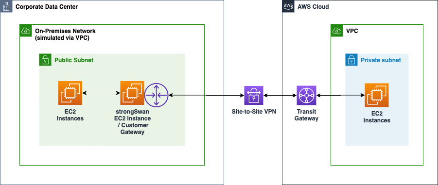
Figure 1: Using strongSwan VPN solution to simulate an on-premises customer gateway
| About this blog post | |
| Time to read | 20 minutes |
| Time to complete | 40 minutes |
| Cost to test the solution | Resources that may incur costs while you run this experiment include:
|
| Learning level | Advanced (300) |
Solution overview
The example CloudFormation template can be useful for demonstrating both:
- Integration with AWS Site-to-Site VPN features and
- Do it yourself site-to-site VPN configurations
You can review the example CloudFormation template at this GitHub repository.
Integration with AWS Site-to-site VPN Features
When you don’t have access to on-premises VPN hardware, this example can be used to demonstrate integration with your networks in AWS using an AWS site-to-site VPN connection. On the remote end of the VPN connection, you can choose to integrate with either AWS Transit Gateways (TGWs) or AWS Virtual Private Gateways (VGWs).
Site-to-site VPN with AWS Transit Gateway
An emerging topology is where your on-premises network establishes a site-to-site VPN connection with an AWS Transit Gateway that acts as a centralized router for multiple VPCs.
An EC2 instance with the strongSwan VPN stack is deployed to a VPC that is simulating a customer’s on-premises network. The EC2 instance is acting as a VPN Customer Gateway in a site-to-site VPN configuration with an AWS Transit Gateway on the other end of the connection are shown in Figure 2.
Figure 2: Site-to-site VPN with AWS Transit Gateway architecture
See AWS Transit Gateway Example: Centralized Router for more details on this topology.
Site-to-site VPN with AWS Virtual Private Gateway
Prior to the advent of AWS Transit Gateway, it was common to connect your site-to-site VPN connection directly to an AWS Virtual Private Gateway (VGW) associated with a single VPC.
An EC2 instance with the strongSwan VPN stack is deployed to a VPC that is simulating a customer’s on-premises network. The EC2 instance is acting as a VPN Customer Gateway in a site-to-site VPN configuration with an AWS Virtual Private Gateway (VGW) on the other end of the connection are shown in Figure 3.
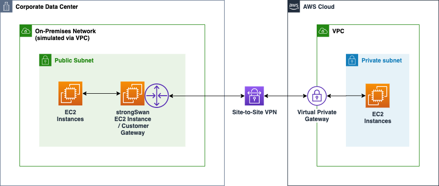
Figure 3: Site-to-site VPN with AWS Virtual Private Gateway architecture
See AWS Site-to-Site VPN for more details on this topology.
Do it yourself site-to-site VPN connection
When use of AWS managed VPN features does not apply, you can use your own VPN solution to establish site-to-site VPN connections.
An EC2 instance with the strongSwan VPN stack is deployed to each VPC. The EC2 instances are connected to each other to form a site-to-site VPN connection are shown in Figure 4.
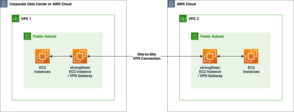
Figure 4: Site-to-site VPN with do it yourself VPN gateways architecture
Integration with AWS services
The CloudFormation template referenced in this post uses the following AWS services and features:
| AWS Service and Features | Description |
| AWS CloudFormation | The strongSwan stack and Quagga components are installed and configured using CloudFormation.CloudFormation provides built-in types including AWS::CloudFormation::Init and AWS::CloudFormation::WaitCondition to automate OS configuration at first boot. |
| Amazon EC2 | The compute service in which the strongSwan VPN gateway is deployed. |
| Amazon CloudWatch Logs | Supports use of a CloudWatch Logs agent that is installed on the strongSwan EC2 instance. This agent is configured to stream OS, VPN gateway, and BGP log data to CloudWatch Logs for centralized monitoring of the complete strongSwan stack. |
| Amazon CloudWatch | Provides a way for EC2 memory and storage metrics to be published and accessed in support of monitoring the VPN gateway. |
| AWS Systems Manager Session Manager | Enables human operators to gain secure terminal access to the strongSwan EC2 Linux OS instance without the need to establish Internet accessible bastion hosts and enable port 22 access to the VPN gateway. |
| AWS Systems Manager Parameter Store | Used to query for latest Amazon Linux 2 Amazon Machine Image (AMI) image that forms the basis of the VPN gateway EC2 instances. |
Setting up the environment
The following steps are oriented toward establishing a Site-to-Site VPN connection with AWS Transit Gateway deployment topology. Minor adjustments to the set up process are required if you’d rather deploy a Site-to-Site VPN with AWS Virtual Private Gateway topology.
If you’d like to set up a do-it-yourself solution where a strongSwan VPN gateway is used on both ends of the site-to-site VPN connection, you should be able to extend these instructions.
The overall steps include:
- Complete prerequisites
- Allocate an Elastic IP address on customer on-premises side
- Configure the AWS side of the VPN connection
- Download the VPN tunnel configuration
- Deploy strongSwan VPN gateway stack to your on-premises VPC
- Monitor VPN connection status
- Test the VPN connection
1. Complete prerequisites
For this configuration, ensure that you satisfy these prerequisites:
- You have an AWS account.
- You’ve selected an AWS Region in which to perform your demonstration.
- You have two VPCs each with at least one subnet.
- A VPC that simulates your on-premises environment. This post assumes that you have at least one public subnet in your on-premises VPC.
- A VPC that represents your AWS cloud environment with at least one subnet. The subnet can be either private or public.
- You have at least basic knowledge of AWS networking and the use of VPCs.
- You have basic familiarity with Linux and the Linux command line so that you can test the site-to-site VPN connection.
2. Allocate an Elastic IP address on customer on-premises side
Allocate an Elastic IP address in your on-premises VPC so that in later steps you can:
- Configure a Customer Gateway in your AWS cloud VPC.
- Provide the static public IP address for your strongSwan VPN gateway EC2 instance in your on-premises network.
Allocate an Elastic IP address:
- Open the Amazon VPC console at https://console.aws.amazon.com/vpc/
- Choose the AWS Region of interest
- In the navigation pane, choose Elastic IPs
- Choose Allocate new address
- Choose Amazon pool
- Choose Allocate
- Select the newly allocated Elastic IP address and note the IP address and its Allocation ID
3. Configure the AWS side of the VPN connection
Next, set up a site-to-site VPN connection in your AWS cloud VPC environment. I use AWS Transit Gateway in these instructions. Alternatively, you can choose to use AWS Virtual Private Gateway. See Getting started in the AWS Site-to-Site VPN documentation for instructions on setting up a virtual private gateway.
Create a transit gateway and site-to-site VPN connection in your AWS cloud environment:
- See Getting started with transit gateways to create a transit gateway for your AWS cloud VPC environment and attach your AWS cloud VPC to it. To keep things simple starting out, you can use the following default settings:

- Update your AWS cloud VPC route table(s) to route your on-premises destined network traffic to the transit gateway. For example, if your on-premises network is 10.0.0.0/16, add a route to the transit gateway:

- Create a Transit Gateway VPN Attachment. See Creating a transit gateway VPN attachment for the instructions to create a site-to-site VPN connection that is integrated with transit gateway. When configuring the attachment:
- Provide a name for the attachment
- Select the Virtual Private Gateway target gateway type
- Choose the option to create a new Customer Gateway.
- Provide the elastic IP address for you customer gateway that you allocated in the previous step.
- Since we’ll be demonstrating the use of dynamic routing via BGP, provide a BGP Autonomous System Number (ASN) associated with your customer gateway. You can either use one that is assigned to your network, or, if you’re only experimenting, you can specify a private ASN in the 64512-65534 range.
- This post does not lead you through how to configure strongSwan to use certificated-based authentication. However, as an option, you can provide the ARN of a certificate provisioned within AWS Certificate Manager to support certificate-based authentication. See How do I create a certificate-based VPN using Site-to-Site VPN? for details on creating a certificate.
- Select the dynamic routing option to demonstrate the use of BGP.
- Accept the default tunnel options unless you want to experiment with the advanced options.
4. Download the VPN tunnel configuration
Within the site-to-site VPN connection resource of your AWS cloud VPC environment, download the VPN configuration file.
- Open the Amazon VPC console at https://console.aws.amazon.com/vpc/
- Choose the AWS Region of interest
- Choose Site-to-Site VPN Connections
- Select the connection of interest, choose Download, choose the Generic option for Vendor, and download the configuration file.
- Review the contents of the configuration file in preparation for the next step.
As you browse the configuration file, you will see configuration settings for two VPN tunnels. You’ll use the tunnel configuration data in the next step when you deploy a strongSwan-based VPN gateway stack in your on-premises VPC.
If you’re using PSK-based authentication, you’ll need to create two secrets in AWS Secrets Manager in your simulated on-premises environment. You can find PSK values in the VPN tunnel configuration file under the “IPSec Tunnel #1” and “IPSec Tunnel #2” sections and “Pre-Shared Key” value. Each of the AWS Secrets Manager secrets for the PSK values must be in the form of psk:<value>, where psk is the key and <value> is the private shared key value.
5. Deploy strongSwan VPN gateway stack to your on-premises VPC
Switch over to your on-premises VPC to set up the customer gateway in the form of a strongSwan VPN gateway stack running on EC2.
When you deploy the CloudFormation stack, you’ll be asked to enter parameter values associated with the VPN connection and specifically for the two tunnels that make up the connection. You’ll need to have the VPN configuration file open as a reference so that you can copy and paste values for the parameters in the CloudFormation stack.
- Open the AWS CloudFormation console at https://console.aws.amazon.com/cloudformation/
- Choose the AWS Region of interest
- Choose Create Stack and choose With new resources
- Choose Upload a template file
- Use your browser to download the
vpn-gateway-strongswan.ymlCloudFormation template file to your local computer - Choose Choose file to select the CloudFormation template file that you downloaded
- Choose Next to proceed to Specify stack details
- Enter a name for your new CloudFormation stack. For example,
vpn-gateway - Specify the required parameters. Ensure that you use the parameters values that are appropriate for your configuration rather than the values shown in the examples below.
CloudFormation Stack Parameter Description System Classification You can choose to override these parameter values if you’d like to customize the naming of AWS resources created by the template. System Environment You can choose to override this parameter value if you’d like to customize the naming of AWS resources created by the template. Authentication Type The type of authentication. Either psk or pubkey. Use pubkey for certificate-based authentication and psk for private shared key-based authentication. VPN Tunnel 1 Open the VPN configuration file that you downloaded earlier. Pre-Shared Key Secret Name Name of secret in AWS Secrets Manager containing the private shared key for tunnel 1.
AWS Secrets Manager secret must be in the form of psk:<value> where psk is the key and <value> is the private shared key value.
See the remote site’s configuration for the “IPSec Tunnel #1” section and “Pre-Shared Key” value.
Virtual Private Gateway Outside IP Address In the “Tunnel Interface Configuration” for tunnel #1, find the “Virtual Private Gateway” in the “Outside IP Addresses” section:

Customer Gateway Inside IP Address Find the “Customer Gateway” in the “Inside IP Addresses” section:

Virtual Private Gateway Inside IP Address Find the “Virtual Private Gateway” in the “Inside IP Addresses” section:

Virtual Private Gateway BGP ASN See the “BGP Configuration Optons” section of the configuration file for the “Virtual Private Gateway ASN”:

BGP Neighbor IP Address See the “BGP Configuration Optons” section of the configuration file for the “Neighbor IP Address”:

VPN Tunnel 2 Address the same parameters types as explained for tunnel 1, but use values taken from the tunnel 2 section of the configuration file. Note that most of the values for tunnel 2 are different from those used to configure tunnel 1. On-premises Network Configuration Settings associated with the configuration of the VPC and other resources that are simulating your on-premises network environment. VPC ID The VPC in which the VPN gateway is to be deployed. VPC CIDR Block Specify the VPC CIDR block of your on-premises environment. This CIDR block will be used by your BGP configuration to advertise routes to the remote transit gateway. Subnet ID for VPN Gateway The subnet in which the VPN gateway is to be deployed. Elastic IP Address Allocation ID Obtain the allocation ID associated with the Elastic IP address that was allocated in a prior step. This is NOT the elastic IP address. It’s the allocation ID. Local VPN Gateway’s BGP ASN Provide the same value as you provided when you configured your customer gateway resource during the process of creating the transit gateway VPN attachment.
You’ll also see this value in the “Customer Gateway ASN” value of each of the tunnels. The same value is used for both tunnels.

- Choose Next to proceed to Configure stack options
- Choose Next to review your stack settings
- Choose Create stack
Wait for creation of the stack to complete. Since the template uses a wait condition, the stack won’t complete until the strongSwan application and other components have been configured and started.
6. Monitor the VPN connection status
Once creation of the stack has completed, monitor the Site-to-Site VPN Connection on the remote site to confirm that the two VPN tunnels have progressed from the DOWN state to the UP state.
It will usually take 3-5 minutes before both tunnels progress to the UP state.
When using dynamic routing and BGP with the strongSwan configuration established using the CloudFormation template, both tunnels should eventually progress to the UP state.
If the VPN gateway configuration is correct, Tunnel 1 will come up first followed several minutes later by Tunnel 2.

If the tunnels don’t come up within 5 or so minutes after your stack has completed, it’s likely that one or more of the tunnel related CloudFormation stack parameters is incorrect. Double check the parameter values. If any are incorrect, delete and recreate the VPN gateway CloudFormation stack. You should not need to delete and recreate the remote site’s transit gateway and VPN resources.
Review CloudWatch logs of the VPN gateway
You can inspect the VPN gateway’s logs via CloudWatch Logs. In the AWS Management Console under the CloudWatch services and CloudWatch Logs, look for a log group that is named similar to: /infra/vpngw/ec2/....
The log files in order of importance are:
cf-init.log– Look for successful execution of the configuration sets from theAWS::CloudFormation::Initsection of the CloudFormation template.charon.log– If CloudFormation initialization looks ok, review the content of this log file to monitor the establishment of the VPN tunnels.
Inspect the strongSwan VPN gateway
If any of the following log files are not present: charon.log, zebra.log, bgpd.log, start a terminal session with the VPN gateway instance and execute a command to display error messages associated with services starting up on the strongSwan EC2 instance.
Since the CloudFormation stack configures the VPN gateway EC2 instance to support terminal access through AWS Systems Manager Session Manager, you can easily connect to the strongSwan EC2 instance via the EC2 portion of the AWS management console.
- Access the EC2 service of the AWS Management Console
- Choose the strongSwan EC2 instance. For example, infra-vpngw-test
- Choose Connect in the upper portion of the console
- Choose the Session Manager option
- Choose Connect
Use the following commands to display errors associated with starting the following services:
You can review the status of the strongSwan application via sudo strongswan status command. Execution of this command should show that both tunnels are connected:
You can inspect the BGP routes that Quagga knows about by executing the sudo vtysh command followed by the show ip bgp summary subcommand. In the following example, the BGP tunnel neighors are listed:
Next, you can inspect the routes by executing the <code<show ip route subcommand. In the following example, 10.4.0.0/19 represents the route advertised by the transit gateway via BGP.
7. Test the VPN connection
Once you’ve confirmed that the two tunnels are in the UP state, you’re ready to test the VPN connection. The simplest means to test the VPN connection is to deploy an Amazon Linux EC2 instance in a subnet in the VPC of the simulated on-premises environment, deploy an EC2 instance in your AWS cloud VPC, and test connectivity between the EC2 instances.
Add a route to your strongSwan instance in your on-premises subnet routing table
Since you’re using BGP, the strongSwan instance will advertise your on-premises routing information to the transit gateway and vice versa. However, that routing information is not propagated to the VPC route tables on either side of the connection.
In your on-premises VPC, ensure that the subnet in which you intend to deploy a test EC2 instance is associated with a VPC route table that routes all traffic destined for the remote side of the VPN connection to the elastic network interface (ENI) of your strongSwan EC2 instance.
Similarly, on the remote side, ensure that the subnet in which you intend to deploy the other test EC2 instance is associated with a VPC route table that routes all traffic destined for your on-premises network to your transit gateway.
An end-to-end testing scenario with two test EC2 instances is shown in Figure 5.
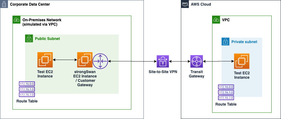
Figure 5: Testing your site-to-site VPN connection using two EC2 instances
Deploy an Amazon Linux EC2 instance to a subnet in each VPC
- Select which method you’d like to use to access your Linux instance:
- Systems Manager Session Manager: No publicly accessible IP address is required. Instead, you can use either AWS Management Console or SSH command line to access your instance. See Getting Started with Session Manager for set up details.
- SSH: Ensure that the security group allows for SSH inbound access and that the instance has a publicly accessible IP address.
- Deploy an Amazon Linux EC2 instance to one each of the two VPCs.
- Ensure the security group includes “All ICMP – IPv4” with a source of the remote network.
Using ping to test connectivity
Use the ping command from either of the two test EC2 instances to validate routing and connectivity between the instances. In the following example, the EC2 instance configured with the address 10.4.15.88 is in the remote environment on the other side of the site-to-site VPN connection. In this example, the ping was successful.
Use the tcpdump command on the target instance to monitor traffic. In the following example, ping or ICMP requests from 10.0.4.26 are flowing into the target instance that has an IP address of 10.4.15.88. ICMP responses are flowing out of the target instance back to the client at 10.0.4.26.
See Testing the Site-to-Site VPN connection for additional tips on testing.
If your ping tests are not successful, verify the following configurations on both sides of the site-to-site VPN connection:
- Ensure that “All ICMP – IPv4” is allowed in the EC2 security group on each of your test EC2 instances.
- Route tables:
- If you are using AWS Transit Gateway, ensure that your remote VPC’s route table has a routing entry to direct on-premises traffic to the transit gateway attachment.
- In your local on-premises VPC, ensure that a route entry directs AWS cloud traffic to the strongSwan EC2 instance’s network interface.
If necessary, consider using tcpdump on the strongSwan VPN gateway EC2 instance to see if traffic is being routed through the gateway.
Advanced scenarios
See the README associated with the CloudFormation template for hints on exercising more advanced capabilities that you might want to explore and demonstrate including:
- Hosting the VPN gateway in a private subnet.
- Updating the VPN gateway stack with configuration changes.
- Replacing the VPN gateway stack with a new stack.
- Routing all Internet destined traffic from your AWS cloud VPC back through the site-to-site VPN connection and out your existing security devices.
- Using certificate-based authentication for AWS site-to-site VPNs.
Cleaning up
To avoid incurring future charges, delete the following resources.
In your simulated on-premises environment:
- Use AWS CloudFormation to delete the stack through which you deployed the strongSWAN VPN gateway.
- If you created an Elastic IP Address in support of the strongSWAN VPN gateway, you can use the EC2 area of the AWS Management Console to delete the Elastic IP address.
- If you created a VPC to simulate the on-premises side of the site-to-site VPN connection and no longer need it, you can consider deleting the VPC and its supporting resources.
- Terminate the test Linux EC2 instance.
In your AWS cloud environment:
- Delete your site-to-site VPN connection.
- Delete your transit gateway.
- Delete your customer gateway.
- Terminate your test Linux EC2 instance.
Conclusion
In this post, I showed how you can you use open source tools in conjunction with AWS services to learn about and experiment with AWS site-to-site VPC capabilities. Using these tools, you can better understand how your organization might use VPN technologies to connect your on-premises network to your AWS environment. After you’ve learned more about the basics of site-to-site VPN capabilities, your deployment can provide you with a means to experiment with more advanced capabilities and features.
If you’d like to learn more about the AWS Site-to-Site VPN services referenced in this example, see the following resources:
If you’d like to learn about using certificate-based authentication with AWS Site-to-Site VPN, take a look at part 2 of this series, Simulating Site-to-Site VPN customer gateways using strongSwan part 2: Certificate-based authentication.

Christopher Kampmeier
Chris is a Senior Solutions Architect working with customers throughout the world who are in the early stages of adopting AWS. Prior to joining AWS, Chris led agile teams to provide builder services to hundreds of delivery teams within a global payment technology solutions provider. In his spare time he enjoys cycling, working on home automation and yard projects, and traveling with his family.