AWS for M&E Blog
How to set up a resilient end-to-end live workflow using AWS Elemental products and services: Part 1
Part 1: Single-region reference architecture deployment walkthrough: The Fundamentals (This Post)
Part 2: Single-region reference architecture deployment walkthrough: Advanced Workflows
Part 3: Multi-regions reference architecture deployment walkthrough: Advanced Workflows
Part 4: High-Availability Advanced Workflows with Automatic Failover
Single-region reference architecture deployment walkthrough: The Fundamentals
In a recent blog post, Kiran Patel described the resiliency challenges generated by high-profile live streaming events, and how AWS Elemental Media Services are architected to overcome those obstacles through distributed and redundant deployments. In this article and the next two chapters, we’ll dive into the details of real-world end-to-end deployments, with a focus on features that impact reliability and strategies for redundancy and monitoring that can stack up to deliver broadcast-grade resilience.
As a starting point, we will create a simple workflow combining two AWS Elemental Live encoders on the ground (for contribution) with several services running in the AWS Cloud: AWS Elemental MediaLive for the live transcoding, AWS Elemental MediaPackage for origination and JIT packaging, and Amazon CloudFront for delivery. (Documentation and training about configuring such workflows from scratch can be found on the “Live Streaming on AWS” webpage and the “AWS Live Streaming and Live-to-VOD Workshop” re:Invent 2017 github page.)
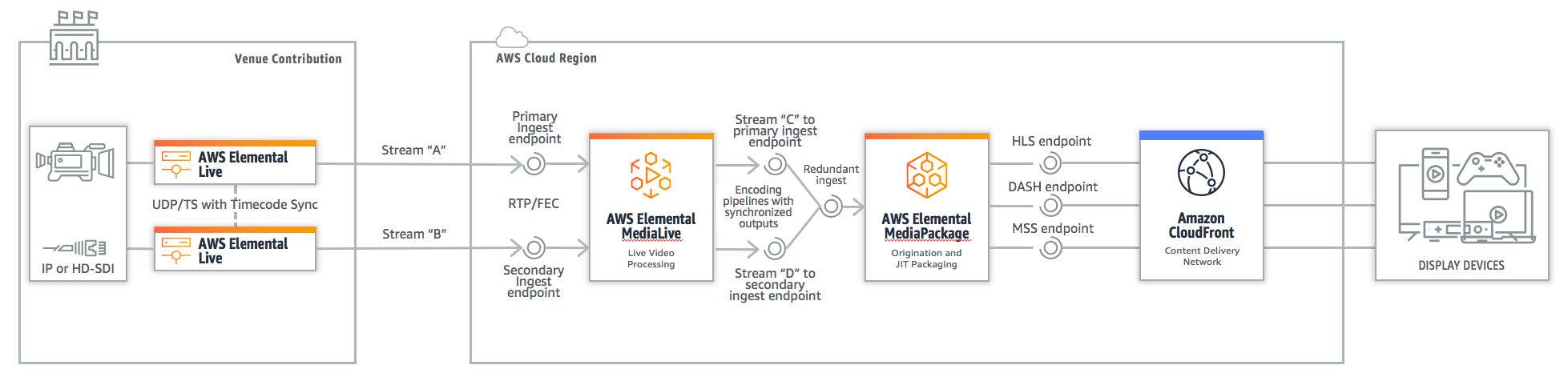
In this workflow, the two AWS Elemental Live encoders are publishing two timecode-synchronized RTP/FEC mezzanine streams (Stream A and Stream B on the diagram) in active/active mode. If one encoder fails, the other continues to operate and its output stream will be leveraged by the downstream workflow.
AWS Elemental MediaLive builds two distinct video transcoding pipelines (in different AWS Availability Zones) from these ingested mezzanine streams and produces all of the necessary ABR renditions (Stream C and Stream D on the diagram) in HLS format, also in active/active mode. The two HLS rendition groups are aligned across segments and group-of-pictures (GOP) boundaries using the two-encoding pipeline’s synchronization feature, based on the input timecodes.
AWS Elemental MediaPackage receives these symmetric ABR renditions groups through its two ingest endpoints (each endpoint being actually supported by redundant instances in different AWS Availability Zones); whenever an HLS segment is missing or takes too long to become available on one ingest endpoint, the MediaPackage input redundancy feature allows it to failover automatically between the streams received on the primary and the secondary input. All final delivery formats are then packaged and encrypted for DRM, if required, on a just-in-time basis, and made available for delivery to the video players and devices through the Amazon CloudFront content delivery network (CDN). If a failover happens, it is transparent to the player, which uses only one streaming URL.
So, let’s get started with this workflow configuration!
Contribution with AWS Elemental Live
In this workflow step, we set up the two synchronized RTP streams that will feed MediaLive with a unified timecode base across the mezzanine streams. The input source can be IP (RTP/FEC or HLS pull) or simply SDI. MediaLive expects its source stream to present a timecode embedded in the video elementary stream (not the RTP layer); in H.264 it’s done by adding pic_timing SEI messages as per section D.1.2 of ISO/IEC 14496-10. In the Elemental Live encoder configuration, this is done in the Output Group Video Encoding section by checking the “Timecode Insertion” option.

Now, let’s see how to feed the timecode insertion option with an actual timecode:
If the source feed is embedding a time reference (which is the recommended scenario): in the Advanced section of the selected Input, select “Embedded” in the Timecode Source menu.

In the Timecode Configuration section, use the “Embedded” option for the Source and check the “Require Initial Timecode” option with a Sync Threshold of 1. This will tell the encoder to load the timecode coming from the source at the initialization of the encoding session, to throw an error if the input timecode is not detected and to permanently resync the output timecode on the input timecode, in order to avoid drifts.

If the source feed doesn’t embed a time reference, you will have to generate one. AWS Elemental Live encoders have a dedicated BNC input for Linear/Longtitudal Timecode (LTC), and it’s easy to generate an audio signal with embedded LTC data in a cost-effective way. The recommended approach here is to genlock your LTC source to the SDI source, in order to guarantee a perfect synchronization of the timecode with the video frames. The fact of not genlocking will expose the LTC signal to be out of phase, which can generate unexpected problems sometimes. If you didn’t acquire a LTC generator with SDI genlock yet, or if you want to experiment with resilient live streaming in your lab, you can simply use an Android or iOS tablet with the appropriate (free) timecode generation application – LTC Timecode Generator on Android and TC Toolbox on iOS – plus a signal distribution cable that you can build from standard cable and adapters. In our setup, we obtained a stable solution by combining a mini-jack-to-XLR stereo cable (plugged into the tablet audio output), an XL-to-BNC adapter, a BNC-Y distributor, and two SDI cables to the encoders. Audio volume must be set to its maximum on the tablet output, and the timecode must be generated with the same FPS settings used for the encoder’s configuration. If you prefer hardware timecode generators, systems like the Tentacle Sync timecode generator are simple to set up and are also reliable. For 50 and 60 FPS framerates, you will need an external timecode generator that supports the SMPTE ST 12-1:2014 revision, which might be more challenging than finding a compliant SDI embedding solution.

In the Timecode Configuration section, use the “External Reference Connector” option for the Source and check the “Require Initial Timecode” option with a Sync Threshold of 1 frame.

A final recommendation about timecodes: by checking the “Enable SDI Information Monitor” in the encoder Settings > Advanced section, you can permanently display the LTC timecode on the top right of the web interface.

Now that you have an input source with a valid timecode, you can set the two remaining options needed for the contribution stream:
Configure one UDP / TS Output Group with Forward Error Correction using 5 rows and 20 columns. It will ensure that your contribution stream is reasonably resilient to packet loss and provides a stable input to MediaLive transcoding. You will notice around 25% bandwidth overhead on top of your stream bitrate.

Configure the primary MediaLive ingest endpoint as the Primary RTP Destination on your first encoder, and the secondary MediaLive ingest endpoint as the Primary RTP Destination on your second encoder.
In the Video Encoding section, go to Advanced > Preprocessors, activate the Timecode Burn-in option, and input different values for your two encoders (like “MAIN“ and “BACKUP“). This will allow you to easily identify which contribution stream is used by MediaPackage at the end of the chain, and to verify that there is no timecode gap when the stream failover happens.

You now can run your Live event on both encoders. If your timecode setup is not functioning, you will see this kind of error message:

If it works correctly, you will notice the Initial timecode being displayed in the Messages panel:

The initial timecode will be different on each encoder as the starting point of the encoding sessions will likely be different, but the timecode of each frame will be identical on the two encoding sessions. MediaLive will rely on the two Live encoders being synchronized to the same timecode to produce its two pipeline-locked HLS ABR sets published to MediaPackage.
Live transcoding with AWS Elemental MediaLive
When it comes to setting up AWS Elemental MediaLive, there are some important parameters to configure with regard to resilience.
In the General Settings > Global Configuration section, you need to set the Output Timing Source to the INPUT_CLOCK and use an empty Input Loss Behavior (through the ‘Don’t include’ option), as we don’t want MediaLive to compensate for an input problem by repeating frames, or inserting color frames or slates, as that would prevent MediaPackage from properly detecting an input problem. In short, we need a sharp cut here.

In the General Settings > Timecode Configuration section, you need to make sure that the timecode source is configured upon the EMBEDDED timecode, and that the output timecode is re-synchronized against the input timecode on every frame, as we did in the Live encoder configuration.

In the General Settings > Channel Logging section, you need to pick the right level of logging that you want to send to CloudWatch; ERROR is fine when in production, as the primary goal is to spot errors in the workflow. In the setup phase, set it to DEBUG to get the full details.
In the Output > HLS Settings section, it is mandatory to set the Input Loss Action to PAUSE_OUTPUT, so that MediaLive stops sending output renditions of a given video pipeline whenever the corresponding mezzanine source stream fails to ingest. MediaPackage will then source automatically from the other ingested stream. You should also INCLUDE the Program Date Time in the Manifest and Segments section.
Once your MediaLive channel is started and your two contribution encoders are publishing their RTP streams, you should see everything in green in the MediaLive dashboard.

In your CloudWatch logs, you should see that the timecodes are present on the input and the output.


If you need to debug a problem at the MediaLive level or validate its HLS output streams, the best approach is to use MediaStore containers as destinations for both output streams and analyze the content of the M3U8 playlists and media segments stored there. (MediaPackage doesn’t provide a passthrough option, which could allow you to analyze the ingested HLS streams.) If you compare the main and backup child playlists, you should see the exact same #EXT-X-PROGRAM-DATE-TIME value and the same segment names and list for a given #EXT-X-MEDIA-SEQUENCE. If you download and play segments from the main and backup streams with the same filename, you should see the same initial timecode burnt in the video. And if you open those segments with DVB Inspector, you’ll see the same PTS and DTS values for the first payload in each segment:

If all those common characteristics are confirmed, it means that your Live + MediaLive combination does actually produce perfectly aligned HLS streams, and that any problems downstream can be diagnosed at the MediaPackage or CDN level.
Live packaging with AWS Elemental MediaPackage
There is nothing special to configure on MediaPackage in order to enable input failover; it’s enabled by default as soon as you provision a channel and ingest two streams.
In order to monitor input switches, you can create a CloudWatch Event with following Event pattern:
{
	"source": [
		"aws.mediapackage"
	],
	"detail-type": [
		"MediaPackage Input Notification"
	]
}
Now let’s simulate a network problem on the primary contribution encoder by unplugging its Ethernet cable. As expected, MediaLive Pipeline A goes into error and video input errors are flagged.

Once the input failover triggers in MediaPackage, you will see the stream label change to “BACKUP” without interruption, and back to “MAIN” once a new problem with the backup pipeline triggers a failover to the main pipeline (assuming you would have plugged again your primary contribution encoder to the network in the meantime, of course).
If you record your desktop and play the video frame by frame in a player like VLC (by enabling View > Advanced Controls), you will be able to verify that the switches between streams are frame-accurate, as we can see in the following screenshots.


The following desktop capture shows the MediaLive console and the MediaPackage preview player side by side: at 0:23 we can see the MAIN>BACKUP switch and the BACKUP>MAIN switch at 2:42.
Content delivery with Amazon CloudFront and your video player
A standard delivery configuration, as described by Lee Atkinson in a recent blog post, won’t require additional effort to set up, as the failover is handled upstream by MediaPackage. Failover won’t impact origin offload rate and delivery performance, as the existing cache footprint is still used for DVR, and the new cached media segments will transparently stack up on top of the existing cache with the same file-naming logic and characteristics. We’ll cover the new CloudFront origin failover feature in an upcoming post in this series, which can be used with AWS Elemental MediaStore to address multi-regions deployments.
With regard to your video player, no change should be required – the failover process is transparent from its perspective, and a unique stream URL is used. Nevertheless, it’s always a good idea to raise your player’s level of resilience to various HTTP errors if its default behavior is to stop requesting segments after a few manifests/playlist errors or timeouts. This is particularly true for low-latency use cases or playback on difficult network conditions in general.
In the next blog post, we will look at how you can maximize your workflow resilience by orchestrating contribution failover with AWS Elemental Conductor Live 3, AWS Elemental MediaLive input switching, and AWS Elemental MediaConnect transport. We’ll also walk through a different kind of resilient workflow with HLS output locking from AWS Elemental Live to AWS Elemental MediaPackage.