AWS Partner Network (APN) Blog
Building a Multi-Tenant SaaS Solution Using Amazon EKS
By Toby Buckley, Sr. Partner Solutions Architect – AWS SaaS Factory
By Ranjith Raman, Sr. Partner Solutions Architect – AWS SaaS Factory
As more organizations make the move to a software-as-a-service (SaaS) delivery model, many are choosing Amazon Elastic Kubernetes Service (Amazon EKS) as the target for their solutions. The programming model, cost efficiency, security, deployment, and operational attributes of EKS represent a compelling model for SaaS providers.
The EKS model also presents SaaS architects and developers with a collection of new multi-tenant considerations. You’ll now have to think about how the core principles of SaaS (isolation, onboarding, identity) are realized in an EKS environment.
To provide a clearer view of how these principles are built, we have created a sample EKS SaaS solution that provides developers and architects with a working example. This illustrates how multi-tenant architecture and design best practices are brought to life in an EKS environment.
In this post, we’ll walk through the key architectural elements of the EKS sample architecture. We’ll look at how to isolate tenants within an EKS cluster, automate tenant onboarding, manage tenant identities, and support routing of tenant workloads.
This solution includes a full working experience with a sample SaaS application and an administration console that manages your SaaS environment.
Explore the EKS SaaS sample solution here >>
Picking an Isolation Model
There are myriad ways to design and build a multi-tenant SaaS solution on Amazon EKS, each with its own set of tradeoffs. With EKS, you have a number of choices that could impact the implementation effort, operational complexity, and cost efficiency.
As an example, some might choose to employ a cluster-per-tenant model to isolate their tenants. This would have a simple isolation story, but may also come with a hefty price tag.
Others might use a shared compute model where all tenants are comingled within the cluster and namespace and isolation is handled at the application level. As you’d expect, this achieves a great deal of operational and cost efficiency; it also represents a less compelling isolation model.
In the middle of these two extremes is namespace-per-tenant isolation, where each tenant is deployed into the same cluster but separated from one another using namespaces and a series of native and add-on Kubernetes constructs. This is what’s commonly referred to as a “silo” model where tenant resources are not shared by tenants.
This namespace-per-tenant model represents a good blend of isolation and cost efficiency. For this reason, we’ve chosen to implement this model in the EKS SaaS sample solution. This choice ends up having a significant impact across our solution, including tenant onboarding, tenant isolation, and the routing of tenant traffic.
High-Level Architecture
Before we dig into the details of the SaaS EKS solution, let’s look at the high-level elements of the architecture that’s employed by this sample solution. Below, you’ll see each of the layers that are part of the EKS SaaS solution.
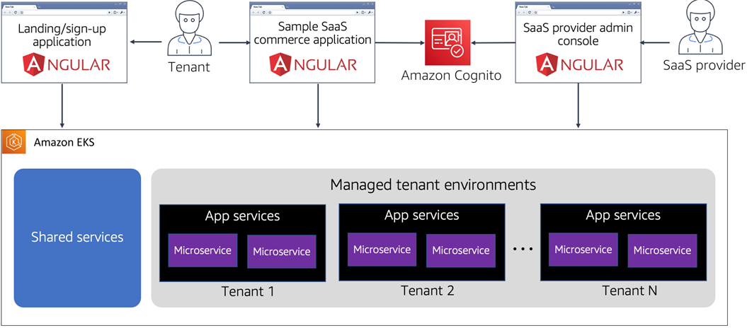
Figure 1 – Conceptual architecture.
First, we have three different flavors of applications that are part of the EKS SaaS experience. These correlate to the common types of applications you’d have in many SaaS environments. The first application, the landing page, represents the public-facing page where customer can find and sign up for our solution. New customers can hit this site, trigger the registration process, and create a new tenant in the system.
The next application is the sample commerce application. Here, we have created a simple e-commerce application that provides some basic order and product functionality while communicating with tenant-specific microservices running in the EKS cluster. This is where you land your multi-tenant SaaS application.
The last application is the SaaS provider administration console. This also uses Amazon Cognito to control access. As the SaaS provider, you’d use this application to configure and manage your tenant policies and settings. Each of these applications interact with services that are running in an EKS cluster.
There are two different categories of services that run in this cluster. First, the shared services layer represents all the common services that needed to support all the operational, management, identity, onboarding, and configuration capabilities of a SaaS environment.
The other category of services is part of the managed tenant environments. The services running here represent the different deployed tenant environments running the microservices of our application. We have separate deployments for each tenant of our system, and we’ll explore the rationale for that architecture decision below.
What Gets Provisioned
Now that we have an understanding of the high-level architecture, let’s dive a level deeper to look at what’s provisioned when installing the EKS SaaS solution.
Baseline Infrastructure
Before we can start to think about tenants and applications, we need to get the baseline version of our environment deployed.
This infrastructure is comprised of the actual EKS cluster that hosts our service. It also includes the required supporting infrastructure, such as AWS Identity and Access Management (IAM) roles, Amazon CloudFront distributions, and backing Amazon Simple Storage Service (Amazon S3) buckets.
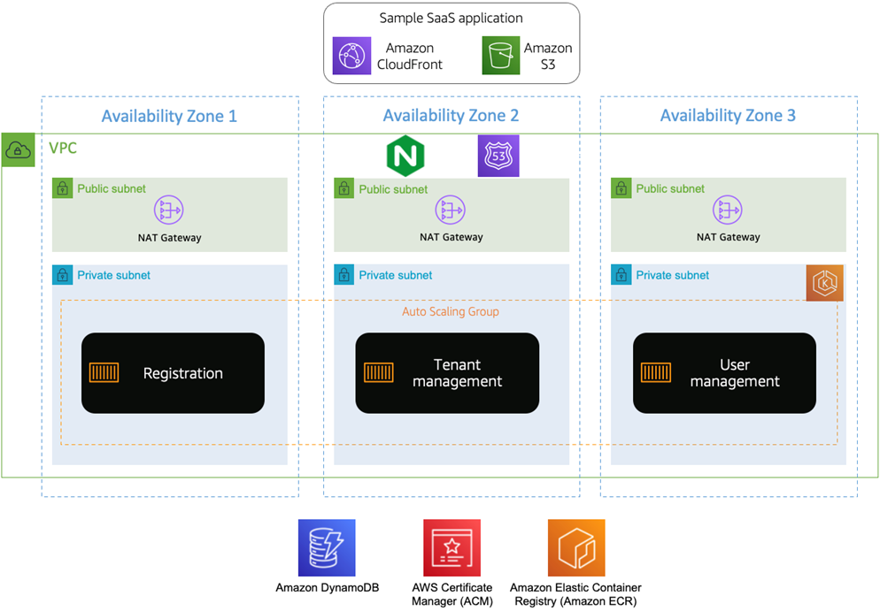
Figure 2 – Baseline infrastructure.
The EKS cluster, along with its corresponding virtual private cloud (VPC), subnets, and network address translation (NAT) gateways, is deployed via the eksctl CLI tool. This command line interface (CLI) streamlines the creation of the various AWS CloudFormation scripts required to deploy a ready-to-use EKS cluster. This cluster runs the shared and the tenant environments of your EKS SaaS solution.
While we’ve leveraged common patterns for configuring and deploying the cluster, you’ll want to think about how to further secure the network and cluster based on the specific needs of your environment. Learn more about best practices for building a fully secured EKS cluster.
Once the cluster is installed, we deploy a number of Kubernetes API objects into the cluster including the open-source NGINX ingress controller and External DNS.
The ingress controller plays a key role helping route multi-tenant requests from client applications. It works in tandem with External DNS, which automatically creates Amazon Route 53 DNS entries for any subdomains referenced in our ingress resources.
In our case, this is only api.DOMAIN.com. The DOMAIN referenced here represents a custom domain you will configure upon deployment.
This baseline architecture includes Amazon S3 and is where each of the web applications presented in this solution are hosted as static websites. We use CloudFront distributions with custom domain names for content distribution. Each website is built and copied to its respective S3 bucket upon deployment.
In addition to the S3 buckets and supporting CloudFront services, the baseline stack provisions a wildcard certificate corresponding to the custom domain name provided when deployed. This certificate is used to provide HTTPS connections to all public web entities in this solution, including the three web applications described above, as well as the public-facing shared and tenant-specific web services.
The setup of this baseline environment also includes the deployment of the shared services portion of our SaaS environment (registration, tenant management, and user management). They support our ability to onboard and manage tenants, and manage admin and tenant users.
The shared services have dependencies on various AWS resources. Tenant management stores and manages tenant information in an Amazon DynamoDB table. User management manages users that are stored in Cognito.
All of the microservices running in EKS are implemented in Java Spring Boot. During the baseline stack’s deployment, an Amazon Elastic Container Registry (Amazon ECR) repository is created for each of the system’s microservices. At deploy time, each service is built and pushed to its respective repo.
As a final step in the baseline configuration, Amazon Route 53 DNS records are added for two of the three web applications in this solution. The admin console is configured as admin.DOMAIN.com and the landing page is configured as www.DOMAIN.com. The sample e-commerce application page doesn’t receive a Route 53 alias until a tenant is deployed.
Tenant Infrastructure
After you have your baseline infrastructure created, you can begin to think more about the infrastructure needed to support tenants as they’re onboarded to your SaaS application.
The architecture we’ve selected here uses a namespace-per-tenant model to implement our isolation, which requires separate resources to be deployed for each tenant. We’ll explore this isolation model in more detail below.
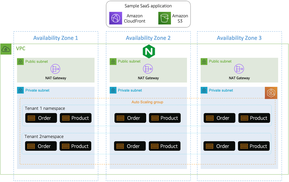
Figure 3 – Deployed tenant microservices.
The architecture above illustrates how the microservices of our application are deployed into our baseline infrastructure. We landed these in the same cluster that was used to deploy the shared services of the environment. The key difference is that none of these microservices and namespaces are created until a tenant actually onboards.
Of course, the constructs needed to bring these microservices to life has more moving parts to it. The following diagram provides a more granular view of the elements of our tenant environments.
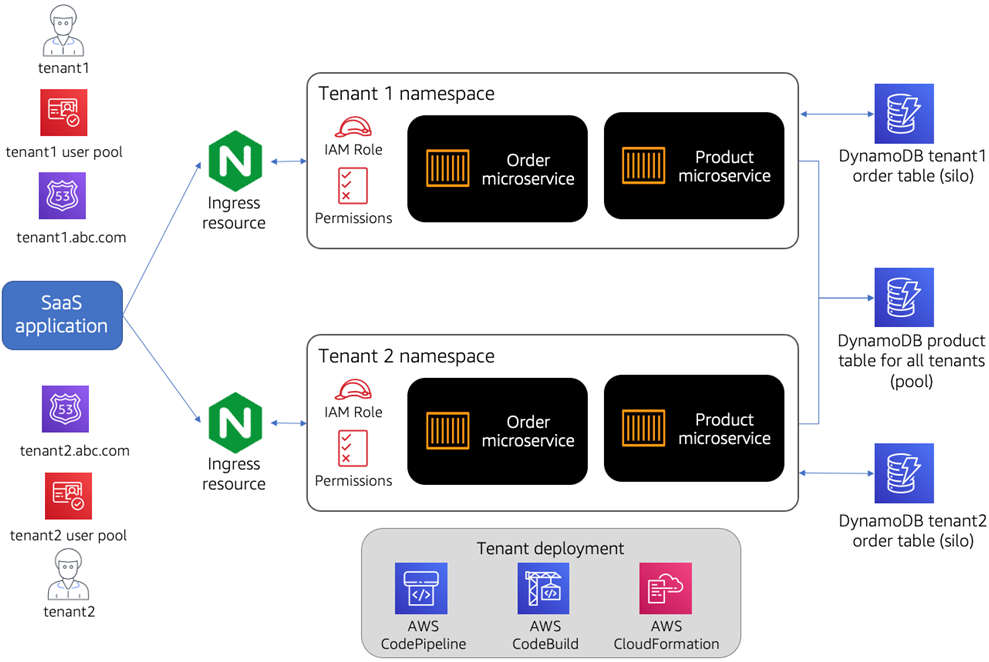
Figure 4 – Per tenant infrastructure.
Looking at the basic flow here, we have the assets used by the SaaS application to access each of our tenant namespaces. Separate user pools and domains are used to authenticate and route tenants into our environment.
As you move further downstream, the solution uses an NGINX ingress controller to route traffic to our namespaces. Another solution that can be used here is the newly-released AWS Load Balancer Controller.
Our order and product services represent the backend for our sample e-commerce application. While these services are deployed from the ECR repository that’s shared by all tenants, each tenant gets their own copy of these microservices, which are configured with tenant-specific information at deploy-time.
All of our tenant-specific artifacts, including the microservices and NGINX ingress resources, are deployed into their own namespace. We assign both an IAM policy for the tenant’s service account, as well as pod and network security policies for additional security.
The AWS Code* services, depicted at the bottom of Figure 4, are used as the “machine” that orchestrates the configuration and deployment of these objects into our EKS cluster. The Code* projects are defined as CloudFormation resources with parameters that serve as placeholders for the tenant-specific data.
To the right, you’ll notice our DynamoDB tables. We wanted to show multiple data partitioning examples in the EKS SaaS solution. Our order microservice, for example, uses a silo storage partitioning model where each tenant has a separate DynamoDB table. A new order table is created for each new tenant that’s added to the system.
The product microservice uses a pooled partitioning model where tenant data is comingled in the same table and accessed via a partition key that’s populated with a tenant identifier.
The order tables are secured with IAM roles that prevent any cross-tenant access. Access to the product tables is also controlled by IAM roles. In this case, we’ve used IAM conditions based on tenant-specific partition keys in the DynamoDB table.
Onboarding Tenants
New tenants are introduced into the system through a frictionless onboarding process that orchestrates all of the services required to get that tenant up and running. Having an automated, low-friction onboarding experience is key to enabling SaaS providers to have a repeatable, scalable mechanism for introducing new tenants.
For this solution, we have a number of moving parts that are included in the onboarding process. First, we must create a new tenant and the administration user for that tenant. Next, we have to configure the Kubernetes namespace and policies for the tenant, and deploy the application microservices into that namespace.
Figure 5 outlines the onboarding flow. The process starts with the filling out a sign-up form, which simulates the typical page you’d offer as the public-facing experience for new tenants. Onboarding can be triggered by the administration application.
We’ve included this flow to illustrate what it would look like to have this same onboarding experience managed by an internal process. The key takeaway is that both of these processes rely on the same underlying mechanism to onboard a tenant to the system.
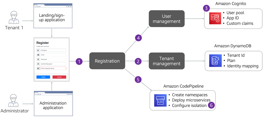
Figure 5 – Tenant onboarding.
The below steps outline the sequence of events that are involved during the tenant onboarding process:
- Tenant registration service receives a request from either the landing page or admin application that includes the tenant’s onboarding data.
- Registration service calls the tenant management service to record tenant details in Amazon DynamoDB.
- Registration service creates a new user pool for the tenant.
- Registration service calls the user management service to create the tenant administration user in the newly-created user pool.
- Registration service kicks off provisioning of tenant’s application services using AWS CodePipeline and AWS CodeBuild to orchestrate the deployment of the tenant’s resources. This includes creating a namespace for the tenant and the deployment of Product and Order microservices to the tenant’s namespace.
- Tenant isolation security policies are applied at network and data level.
Beyond Namespace Isolation
As described earlier, we use a namespace-per-tenant model to create an isolation layer for tenants and their resources within an Amazon EKS cluster.
A Kubernetes namespace by default doesn’t provide a hard isolation boundary for resources that are within that namespace, however. We must introduce additional constructs to prevent any cross-tenant access.
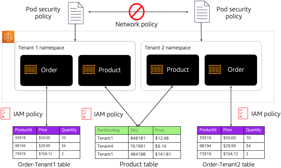
Figure 6 – Tenant isolation.
In this example, we have used pod security and network policies to prevent cross-tenant access at the pod namespace level. We’ve used IAM roles for Service Account to enforce isolation.
This approach introduces credential isolation, ensuring that such that a container can only retrieve credentials for the IAM role that’s associated with the service account to which it belongs. This means a container can never access credentials that for a container that belongs to another pod running in another namespace.
As you move down the diagram in Figure 6, you can see how we apply isolation as each namespace attempts to access other tenant resource (in this case, DynamoDB tables). There are two different variation of isolation for the product and order tables.
For our order microservice, each tenant has a separate order table (using a silo storage model). We have IAM policies that constrain access at the table level.
The product microservice has a single table for all tenants. In this scenario, our IAM policies constraint access to the actual items within the table.
While these constructs help enforce our isolation model, you also need to think about how to isolate at the network level. By default, all pod-to-pod traffic in Kubernetes is allowed and, with no controls in place, all pods can freely communicate with all other pods within and across namespaces in an EKS cluster.
To prevent this cross-namespace access situation, we have implemented network policies using Tigera Calico, which enables us to achieve network isolation by applying fine-grained network policies at the namespace level.
Conclusion
This post examines some of the key considerations that can influence how you approach designing and building a SaaS solution with Amazon EKS. It should be clear that the power and flexibility of EKS also requires you to find creative ways to realize some of the core architectural principles of SaaS.
As you dig into the EKS SaaS sample application we presented here, you’ll get a better sense of the overall end-to-end experience of building a complete working EKS SaaS solution on AWS. This should give you a good head start while still allowing you to shape it around the policies that align with the needs of your SaaS environment.
For a more in-depth view of this solution, we invite you to take a look at the solution repo. There, you’ll find step-by-step deployment instructions, as well as a more development-centric guide to assist with understanding all of the moving pieces of the environment.
About AWS SaaS Factory
AWS SaaS Factory helps organizations at any stage of the SaaS journey. Whether looking to build new products, migrate existing applications, or optimize SaaS solutions on AWS, we can help. Visit the AWS SaaS Factory Insights Hub to discover more technical and business content and best practices.
SaaS builders are encouraged to reach out to their account representative to inquire about engagement models and to work with the AWS SaaS Factory team.
Sign up to stay informed about the latest SaaS on AWS news, resources, and events.