AWS Partner Network (APN) Blog
Provide Enhanced Security for Web Servers in VMware Cloud on AWS Using AWS WAF
By Craig Herring, Sr. Specialist Solutions Architect – VMware Cloud on AWS
Web attacks have continuously been on the incline as more and more companies provide online and remote connectivity for their applications. Ensuring these applications, and company assets, are protected from ransomware, bots, DDoS, SQL injection, scripting and attacks, and other risks is extremely important.
Over the years, the tech industry has created various types of ransomware and attack recovery methods. Mitigating these attacks before they happen can remove the expensive process of recovering from impact to data and the business. Introducing advanced security controls can mitigate data loss and downtime as a result of these attacks.
As you consider migrating to VMware Cloud on AWS or have already done so, you could have the requirement to protect web servers residing in a vSphere environment on the Amazon Web Services (AWS) global infrastructure.
To provide one aspect of security for these workloads, you can leverage some native AWS services. Depending on your architecture, traditional on-premises web application firewalls and load balancers may not function in the same way in VMware Cloud on AWS. To solve for this, you can leverage the AWS WAF, a web application firewall that helps protect your apps or APIs against common web exploits and bots.
VMware Cloud on AWS is a fully managed service jointly engineered by AWS and VMware. It provides a VMware software-defined data center (SDDC) infrastructure with the same look and feel as many companies’ on-premises vSphere infrastructures. It also includes software-defined storage and networking technologies by VMware vSAN and VMware NSX.
AWS WAF provides scanning of designated HTTP/HTTPS traffic to protect against various attacks. WAF ACL rulesets define acceptable or malicious traffic and can be updated within minutes across all AWS WAF deployments leveraging AWS Firewall Manager.
Pre-configured rulesets are available by AWS through the WAF ACL console, or third-party rulesets can be purchased through AWS Marketplace. Other security controls are also available for use with AWS WAF, and Amazon CloudWatch can be used for monitoring metrics, logs, and alerts.
Design Considerations
As we begin to build out these services, some design decisions need to be made, such as providing an AWS region and Availability Zone (AZ) for our infrastructure components. This includes VMware Cloud on AWS SDDC(s), native Amazon Virtual Private Clouds (VPCs), and potentially other supporting native AWS services.
When determining these locations, consider the locations the services will be accessed from. For example, if users reside on the east coast of the United States, we would create these services in the us-east-1 or us-east-2 regions. Similarly, if users reside on the west coast or in Europe, we’d create these services in the closest respective regions. If users are in multiple regions, we may consider a multi-regional design.
AWS CloudFront provides global delivery capabilities and is a content distribution service that can deliver content much closer to end users through more than 225 points of presence (PoPs). For this example, we will choose an Application Load Balancer (ALB). Other design considerations include how our web application will operate in VMware Cloud on AWS and how the traffic will flow from the internet to connect to the web servers.
The design decisions we’ll make for this configuration are:
- Regions: us-east-2, us-west-2
- Availability zones: 4
- VPCs: 2
- Network subnets: 8 (AWS-native and VMware Cloud on AWS SDDC network segments)
- VMware Cloud on AWS: 4 SDDCs, 1 in each AZ
- Database, application, and web servers reside within each SDDC. Database replication through VMware Transit Connect.
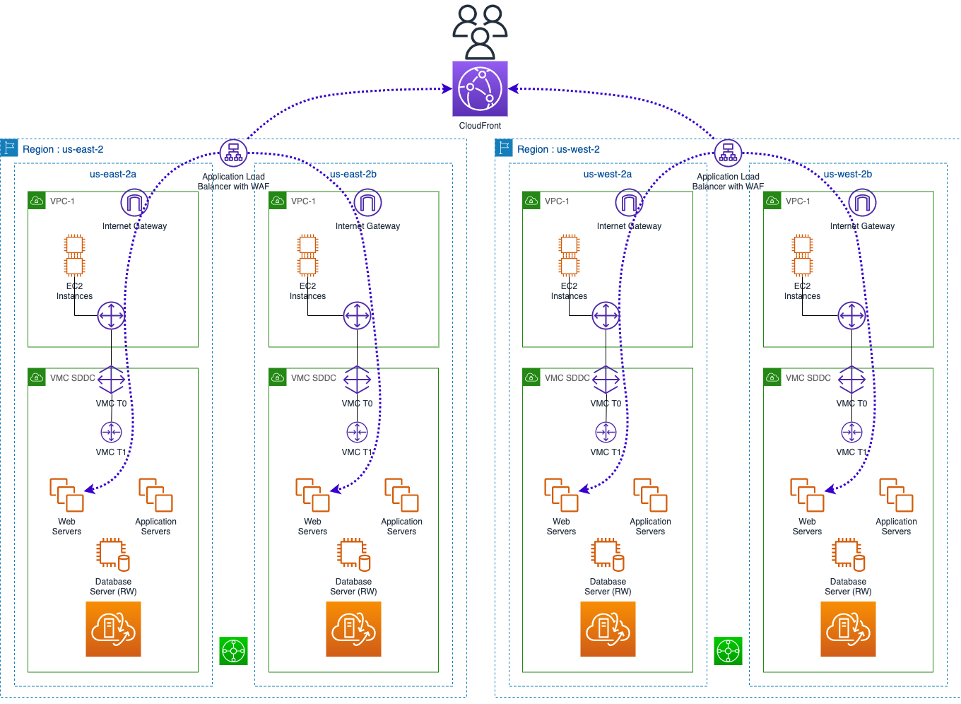
Figure 1 – Application Load Balancer + WAF integration with VMware Cloud on AWS.
Implementation Summary
Once you have the foundational design decisions noted, the implementation will follow this process.
VPC Deployment
Creation of a VPC in each region that spans at least two Availability Zones. This creates redundancy and resiliency in the event a single AZ has a failure or an entire region is experiencing issues. You have the option to create a VPC through manual methods where you’ll be required to create subnets, route tables, and network connections. The other option creates these objects for you after defining a couple different options.
SDDC Deployment
You will deploy the VMware Cloud on AWS SDDCs in each AZ where you have deployed the VPCs. Each SDDC will need to be connected either via a connected VPC or by leveraging VMware Transit Connect or AWS Transit Gateway. Depending on your use case, other architecture considerations may be required for your deployment. The least complex would be to leverage a connected VPC architecture as shown in Figure 2 below.
Next, deploy the SDDCs and continue the setup while they are being created. This process can take up to two hours to complete for each SDDC, and they can be deployed in parallel. SDDC deployments are executed within the VMware Cloud Console.
While the SDDCs are created, continue the setup for the rest of the environment. You will create the Amazon Elastic Compute Cloud (Amazon EC2) target group, and based on our design decision of web servers residing in a SDDC network segment you’ll choose the target group type IP Address.
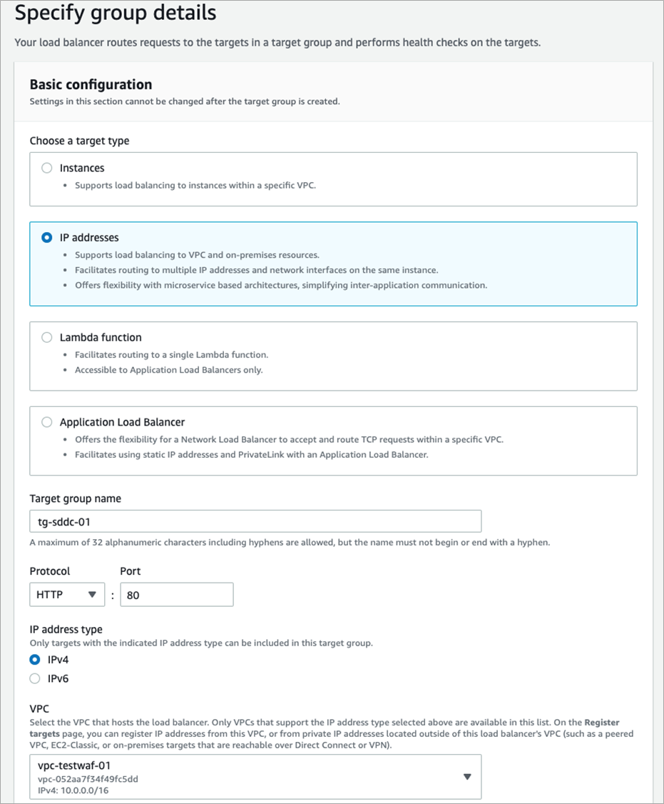
Figure 2 – Target group creation.
Provide a target name, choose the VPC this will be associated with, and insert the appropriate health check path. In the event you have more than four web servers to load balance, multiple target groups can be created and associated to the Application Load Balancer (ALB).

Figure 3 – Health check path designation.
In the next step, choose Other private IP address for Step 1. Then add the specific targets that reside within the SDDC segments. The targets are the IP addresses of the web servers.
Select Include as pending below, and the final dialogue box allows you to view the target summary.

Figure 4 – Target IP creation.
Next, create an Application Load Balancer and ensure the internet-facing scheme is chosen. Select the VPC this will be attached to and select the subnets this load balancer will provide services to.
Select the security group to allow web traffic to pass through. Finally, select the target group for the listener created in the previous step.

Figure 5 – Application Load Balancer creation.
To attach security controls to the ALB, create web ACLs for the WAF. You can find these either by searching for the AWS WAF and AWS Shield services, or selecting the link inside the Integrated Services tab of the ALB.
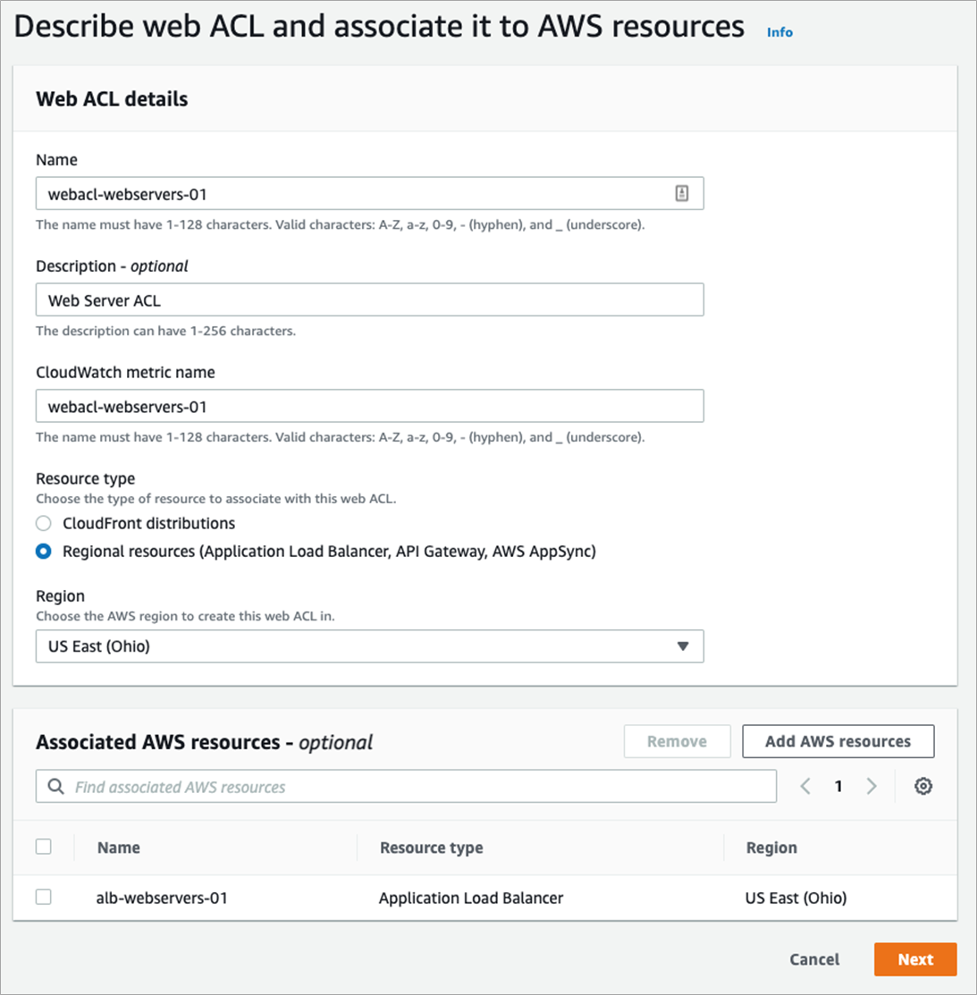
Figure 6 – WAF Web ACL configuration.
When creating a WAF ACL, you will set the name, Amazon CloudWatch metric name, and for this example Resource type – Regional resource. This ACL can attach to one of three resource types, and in this example, you’ll choose the ALB created in the previous step.
The next screen allows you to define the specific rules that will be used to protect your web servers. Within Add rules, add your own rules as well as managed rules from AWS or a third party.

Figure 7 – WAF rules definitions.
The next steps allow you to choose the rule priority and Amazon CloudWatch metrics. The final step allows you to configure the specific rule metrics and sampling options.
The last component to deploy is Amazon CloudFront, which enables you to deliver the content from across AZs or even regions and enhances the security of your applications by adding a number of protective features. This service will tie our two regions together in delivering content to your users.
Once the SDDCs are deployed, create an SDDC group that will allow traffic to flow between both SDDCs via Transit Connect for database replication and other application communication. In a later step, you will also add the appropriate NSX-T security policies.
Once this has completed, create the network segment in each SDDC the web, application, and database servers will reside in. You’ll also notice default network segments that are created during the SDDC creation. These can be deleted as they could overlap with another network subnet inside your environment.
The following networks were created for this example.
- Webserver-lab-01
- Subnet: 10.10.10.1/24
- DHCP: Gateway DHCP Server
- DHCP Range: 10.10.10.10-10.10.10.250
- Webserver-lab-02
- Subnet: 10.11.10.1/24
- DHCP: Gateway DHCP Server
- DHCP Range: 10.11.10.10-10.11.10.250
Next, create a virtual machine (VM) member group for the web servers that will be associated with security policies. Here, a compute group was created and members were defined by the VM name. In this example, “VM group begins with” with input as “lab-web” was used. VMs can be deployed manually with this name, or a service like vRealize Automation Cloud can use automation for setting VM names.
Next, routes can be checked between both environments to ensure they have propagated properly. These can be viewed in the Networking & Security item under Transit Connect. Other routes from Transit Connect can be viewed under the SDDC group under the Routing menu.
You can choose the members and external tables from the drop-down menu, and VPC routing table can be checked for the VPC attached route table. The NSX-T network segments should be propagated to the attached VPC. Ensure you add ACLs to allow traffic flow from the ALB to the SDDC network segments.
You will need to allow traffic to flow from the SDDC network segments to the VPC ALB and ultimately to the internet. To accomplish this, add policies to both the SDDC compute gateway and distributed firewall as shown below.
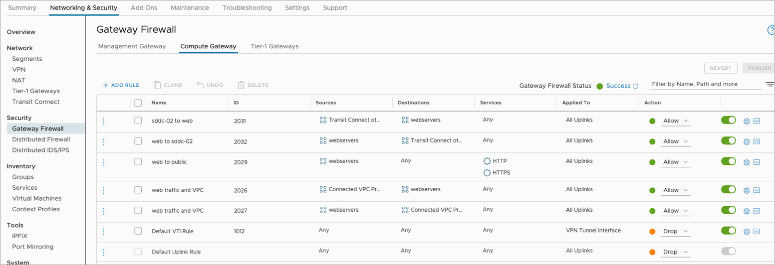
Figure 8 – Gateway firewall rules example.
Similar to the above diagram, additional rules are required within the Distributed Firewall Security section. These allow the web servers to communicate with the AWS Application Load Balancer.
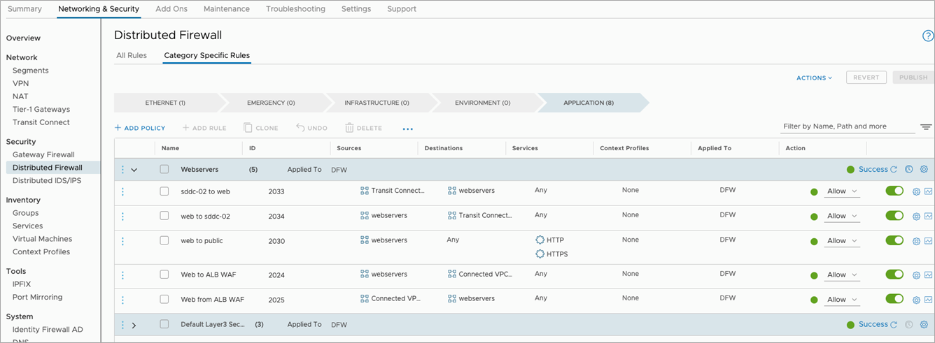
Figure 9 – Distributed firewall rules example.
The final steps are to deploy the VMs and add the IP addresses to the target group that is associated to the ALB.
Conclusion
In this post, I covered how to integrate AWS WAF policies associated to an Application Load Balancer to provide additional security for web applications that reside within VMware Cloud on AWS. Optionally, you can incorporate Amazon EC2-based web application instances to balance your application in both the SDDC and EC2.